I wanted to attach a knob to my Raspberry Pi to act as a volume control for my MPD based jukebox. Traditionally volume control devices are implemented with potentiometers acting as inputs for amplifiers. A potentiometer is a hardware device with a knob or a slider that, in a word allows for a variable voltage input into a circuit. 1 The problem here is that this is a very hardware oriented method of setting volume, when what I really wanted to do was set the software volume setting on the Raspberry Pi. I wanted to be able to change the volume from the operating system (a la alsamixer) or through the MPD client, and still be able change it up or down by physically turning the knob on the device. Essentially, I wanted the ALSA PCM element volume to increase as I turned the knob clockwise, and decrease as I turned the knob counterclockwise, I wanted to actual volume to be independent of the position of the knob and because a potentiometer is an absolute input device which returns it’s position and cannot be turned indefinitely there was no way to make one work for what I needed.
What I needed was a rotary encoder. A rotary encoder, is in essence a pair of switches which change as a shaft is turned, and by reading those switches, one can tell whether and in which direction the shaft is turning. A rotary encoder cannot tell absolute position, but it doesn’t need to, plus it can spin infinitely.2 This, of course, was exactly what I needed. Unfortunately there isn’t a lot of information on getting a rotary encoder working with a Raspberry Pi.
I did some research and found a number of articles about getting a rotary encoder to work with an Arduino. This code could be adapted to the Raspberry Pi, but it’s important to note that an Arduino has a real-time operating system (that is, it has almost no operating system) so programs can execute without the unpredictable delays of time-sharing/multitasking, buffering, or garbage collection. The Raspberry Pi is a Linux machine, which is a time-sharing system, so it can’t make guarantees to the millisecond about performance the same way an Arduino can. This can be a problem because to properly read a rotary encoder, a program needs to track every change of the switches, else one could get backward or confused readings.
Fortunately this is a solvable problem. The Raspberry Pi has interrupts, which allows us to trigger functions upon switch reading changes, and the wiringPi library makes it easy to use them. So, here’s what I ultimately did:
Connecting a rotary encoder couldn’t be much simpler. Rotary encoders only have three pins.3 The middle pin is ground and the others are connected to the switches and produce the A signal and B signal respectively. You can connect these pins to the Raspberry Pi directly. Rotary Encoder pins:
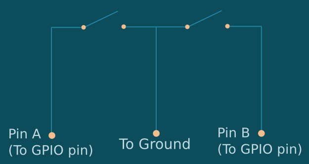
And how to connect it to the Raspberry Pi:
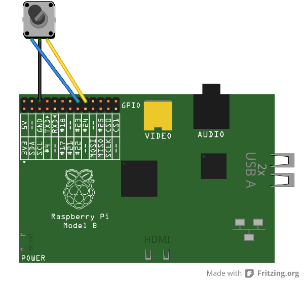
Using the built in pull-up resistors on the Raspberry Pi for the pins connected to A and B means that when the respective switches are closed, the pins will read low (0) and when the switches are open, the same pins will read high (1). There’s no need for any additional resistors or capacitors. As the encoder shaft is turned, the switches will alternatively open and close so that they progress through a series of states known as Gray Code. These states are as follows:
00, 01, 11, 10
By reading any two successive states, one can tell which direction the encoder is turning. 00->01 might be clockwise while 00->10 might be counter-clockwise. Using interrupts, we can get the Pi to record each change of a pin and to record the direction the encoder is turning. Here’s my code:
//rotaryencoder.h
//17 pins / 2 pins per encoder = 8 maximum encoders
#define max_encoders 8

struct encoder
{
    int pin_a;
    int pin_b;
    volatile long value;
    volatile int lastEncoded;
};

//Pre-allocate encoder objects on the stack so we don't have to
//worry about freeing them
struct encoder encoders[max_encoders];

/*
  Should be run for every rotary encoder you want to control
  Returns a pointer to the new rotary encoder structer
  The pointer will be NULL is the function failed for any reason
*/
struct encoder *setupencoder(int pin_a, int pin_b);
and:
//rotaryencoder.c
#include <wiringPi.h>

#include <stdio.h>
#include <stdlib.h>
#include <stdint.h>

#include "rotaryencoder.h"

int numberofencoders = 0;

void updateEncoders()
{
    struct encoder *encoder = encoders;
    for (; encoder < encoders + numberofencoders; encoder++)
    {
        int MSB = digitalRead(encoder->pin_a);
        int LSB = digitalRead(encoder->pin_b);

        int encoded = (MSB << 1) | LSB;
        int sum = (encoder->lastEncoded << 2) | encoded;

        if(sum == 0b1101 || sum == 0b0100 || sum == 0b0010 || sum == 0b1011) encoder->value++;
        if(sum == 0b1110 || sum == 0b0111 || sum == 0b0001 || sum == 0b1000) encoder->value--;

        encoder->lastEncoded = encoded;
    }
}

struct encoder *setupencoder(int pin_a, int pin_b)
{
    if (numberofencoders > max_encoders)
    {
        printf("Maximum number of encodered exceded: %i\n", max_encoders);
        return NULL;
    }

    struct encoder *newencoder = encoders + numberofencoders++;
    newencoder->pin_a = pin_a;
    newencoder->pin_b = pin_b;
    newencoder->value = 0;
    newencoder->lastEncoded = 0;

    pinMode(pin_a, INPUT);
    pinMode(pin_b, INPUT);
    pullUpDnControl(pin_a, PUD_UP);
    pullUpDnControl(pin_b, PUD_UP);
    wiringPiISR(pin_a,INT_EDGE_BOTH, updateEncoders);
    wiringPiISR(pin_b,INT_EDGE_BOTH, updateEncoders);

    return newencoder;
}
This is a library, so I can include it in my project with the code:
#include "rotaryencoder.h"
And by making sure to include the library at compile time (eg):
gcc -lwiringPi program.c rotaryencoder.c
I can setup a new encoder using the code:
struct encoder *encoder = setupencoder(pin_a, pin_b);
And I can then get the current rotation of the encoder with:
encoder->value;
That’s all there is to it. The encoder object is allocated on the stack (Eight are pre-allocated, which is the maximum number you possibly use,) so there is no need to free them. Simply query the current rotation with “encoder->value” whenever you need it.
I put my code on Github so you can get it here: https://github.com/astine/rotaryencoder/blob/master/rotaryencoder.c
- Potentiometers are called ‘pots’ for short and their very common. You probably interact with them every day even if you don’t know it. If you’ve ever used a physical volume control on an amplifier or a pair of speakers or an amplifier or a knob on a dimmer switch, that knob was probable attached to a ‘pot’. ↩
- Rotary encoders are probably nearly as common as pots, but they only work with digital devices. If the knob spins infinitely, it might be rotary encoder. ↩
- unless the encoder has a built-in press switch or led, which many do. ↩